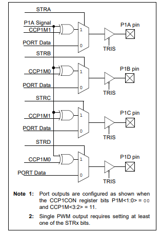
CCP1 can generate PWM signal up to 4 pins at the same time, by selecting CCP1M<3:2> = 11 and P1M<1:0> = 00. The Pulse Steering Control Register (PSTRCON) allow us to select any streering pin between P1A, P1B, P1C, and P1D.
 |
| PSTRCON: PULSE STEERING CONTROL REGISTER |
 |
| SIMPLIFIED STEERING BLOCK DIAGRAM |
In this example, I use all PWM steering pins to generate the signal of 25% duty cycle.
void main() {
     TRISC=0x01;
     TRISD=0x00;
     OSCCON=0x70;
     CCP1CON=0x3C;
     PSTRCON=0x0F;             // steering output to P1<D:A>
     PR2=99;                   // Period is 50us
     CCPR1L=22;               // duty cycle is 25%
     T2CON=0x00;             // Timer2 Prescaler is 1:1
     TMR2=0;                   // clear timer 2
     T2CON.TMR2ON=1;          // Enable timer2
     PIR1.TMR2IF=0;             // clear flag
     while(PIR1.TMR2IF==0);     // wait until new cycles
}
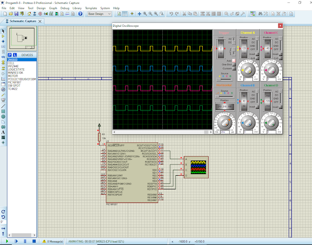
I use simulator to test this program.
 |
| Program simulation |
This system uses a 8MHz internal RC oscillator of PIC16F887.
No comments:
Post a Comment