Overview
CH340 is a series of USB to UART converter IC. There are six options within this family. This chip is popular within some Arduino board, nodeMCU board module etc. I bought five of CH340G for my own esp8266 firmware flushing board in 2019 for a few Dollars. Finally it works well.
 |
| A commercial sample of CH340G |
 |
| Various CH340 chips pins diagram |
The USB version of this chip is USB 2.0 . It's supply from both 3.3V or 5V source. Data transmission could take up to 2 Mbps.
Referring to the serial communication, the data rate ranges from 2400bps to 115200bps.
In CH340G there are up to 16 pins. But I show only some important pin to know in this this design.
- GND - Supply ground at pin 1
- TXD - CH340G Transmit at pin 2
- RXD - CH340G Receive at pin 3
- V3 - Regulated +3.3V supply voltage
- D+ - Data+
- D- - Data-
- XI and XO - 12MHz crystal pins
- V5 - +5V supply voltage
Other remanding pins are serial port pin functions that I don't want show them here due to a rich of web-based resources.
Schematic And PCB Design
In this design I make a very simple USB to UART converter with only Transmit (Tx) and Receive (Rx) pin. The design works at 5V.
Since in the EDA software I use for design doesn't have CH340 chip. So I made my own symbol following the original device pins diagram from the vendor. This video shows about the process of making a symbol of CH340 for schematic design.
I use a USB type-B connector for USB to Host communication due to the stock components I stock.
 |
| Schematic Diagram |
 |
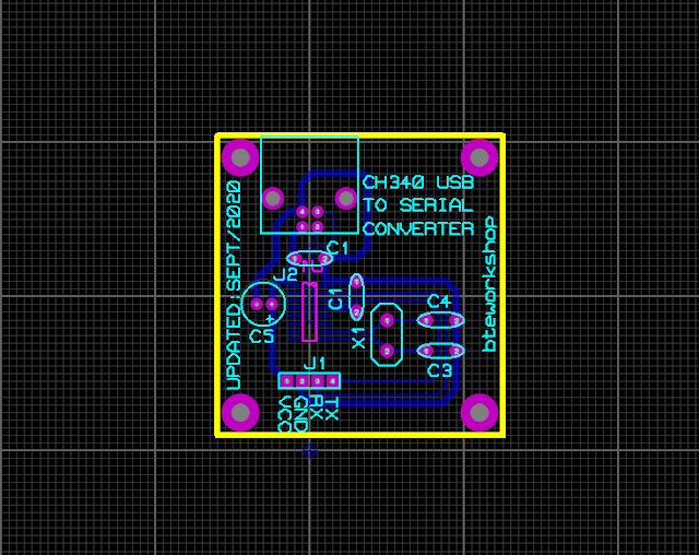
| PCB design view |
 |
| PCB pattern |
 |
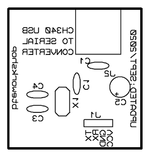
| Component side |
 |
| A 3D View of this design |
Click here if you wish to download a zip of this Proteus 8 design. This video shows about the schematic and PCB design.
No comments:
Post a Comment