DIY PCB Project, CPLD/FPGA Coding with VHDL, Arduino Programming Tutorials, PLC Programming Tutorials, PIC Microcontroller Programming Tutorials and Projects, AVR Microcontroller Programming Tutorials, etc.
Pages
▼
Sunday, August 23, 2020
Making A Simple Single SPDT Relay Board Module For PIC AVR And Arduino
Overview
An electro-mechanical relay module board is widely available from any online store. It costs around 1 US Dollars. The working voltage ranges from 3.3 V to 24 V. For Arduino users, a 3.3 V or a 5 V relay relay module are very popular due to a USB-powered bus, during the prototyping. However, a lower voltage rating of a relay draws a higher current.
A four-channel relay module board I ordered from an on line store. The working voltage is 5 V.
A single pole dual throws (SPDT) relay is very popular over the other contact typologies. This kind of relay comes with 5 pins.
Designing A Relay Module Board
Using my own existing components in-stock with an in-house PCB prototyping, making a DIY relay module board is very straight forward. For a few requirements, all components are solder on a strip board without the circuit and PCB design.
For a long term design requirements, I use an EDA tool to design the circuit and PCB. The PCB are made from copper clad board with the etching process.
Schematic Diagram, The relay is selected to work with 12 V DC due to a high power requirement.
A sample of completed PCB design
Copper track at the bottom
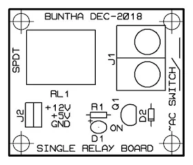
Top silk of the components legend
A 3D Model renders by the Software.
Component Side
Copper Side
Click here to download the complete design file in Proteus 8.


No comments:
Post a Comment